5 & 10 MHz WWV TRF Receivers for Frequency Counter Calibration (and now also 3.33 and 7.85 MHz CHU)
5 & 10 MHz WWV TRF receivers designed by WD8DSB which appeared in the February 2018 issue of QST
Download Copy Of QST Article (by permission of ARRL): https://drive.google.com/file/d/1EiiiGGT2So_oVRcUDGHq2z_ObGERVLaE/view?usp=sharing
Here is a link to a YouTube video that shows the receivers in action: http://www.youtube.com/watch?v=u0HAkMoAIoA&feature=youtu.be
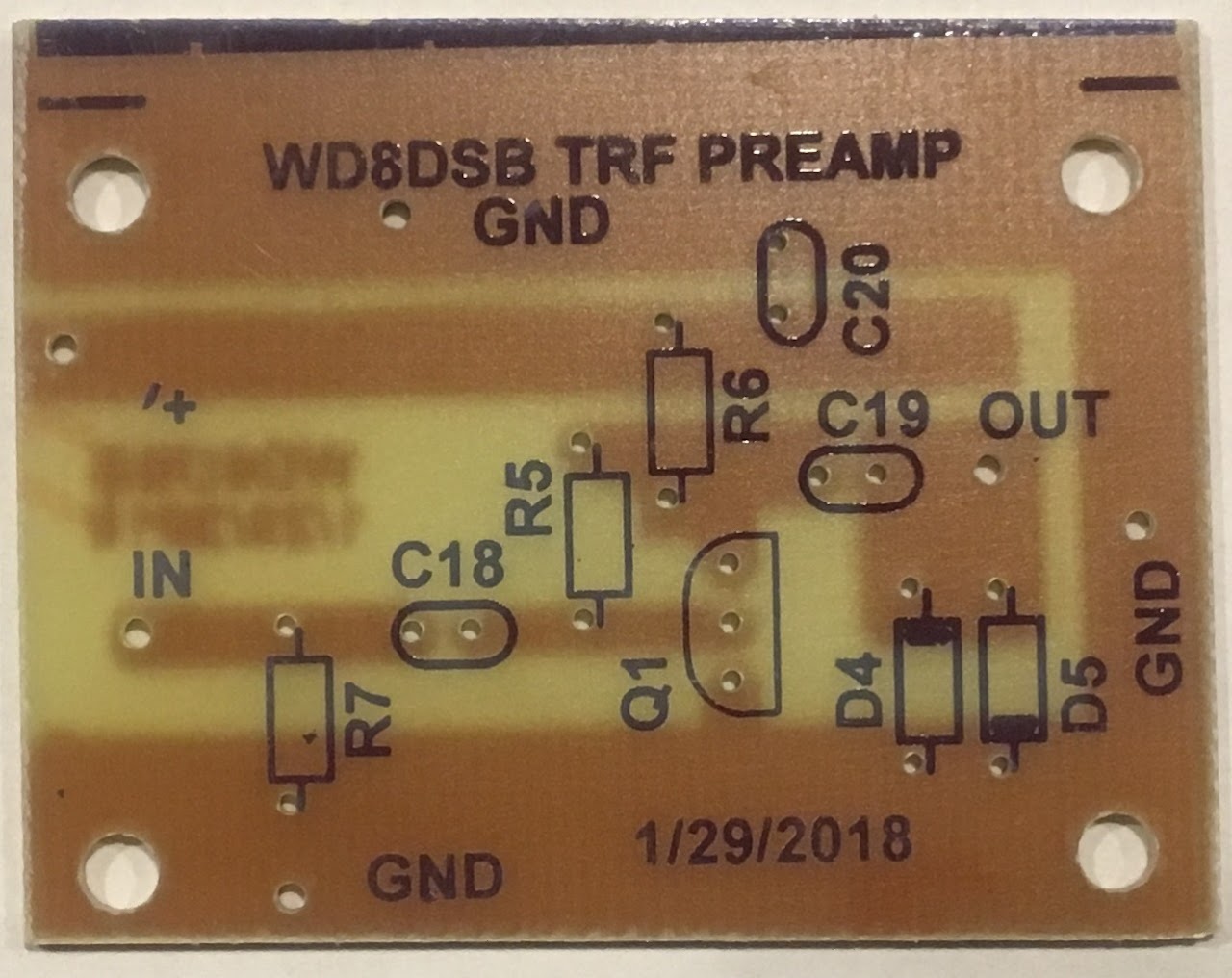
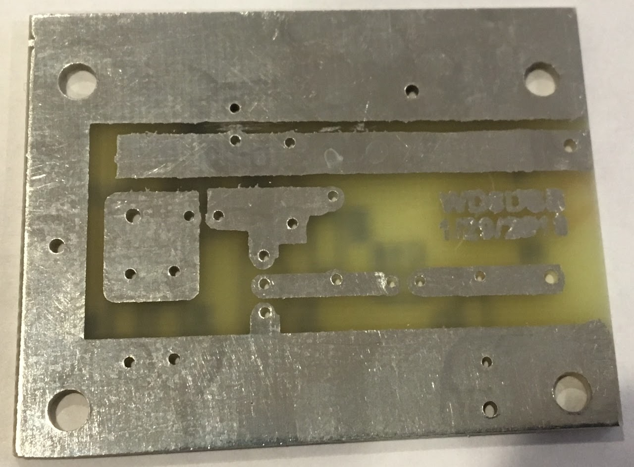
Update Feb 6, 2018: Far Circuits is now offering etched and drilled circuit boards for both my WWV TRF receiver and TRF preamp ($4 per board plus shipping, $7.50 for both boards if purchased at the same time plus shipping). Pictures of preamp board top and bottom shown below. For more information visit the Far Circuits web page at:http://www.farcircuits.net/RECEIVERS%20AND%20RECEIVER%20PERAMP.htm
Note: The Far Circuits WWV TRF receiver board does not have high end features like a solder mask, nevertheless it's functionally (electrically) the same as my original boards that I had etched by basicpcb.com.
--------------------------------------------------------------------------------------------------------------------------
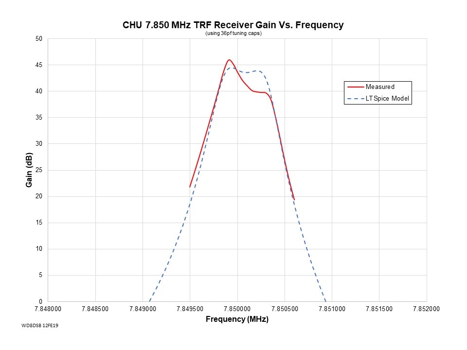
I went ahead and investigated the possibility of using the Canadian time and frequency standard station CHU in place of WWV. The CHU signal is a constant carrier signal, and therefore it's an ideal alternative for use with my basic TRF receiver design. I designed my first CHU TRF receiver for the CHU transmitter on 7.85 MHz, and had custom crystals made by a company in the U.K. called QuartsLab since I could not find off the shelf 7.85 MHz crystals. The QuartsLab website URL is http://www.quartslab.com/ . While the cost of custom made crystals is not cheap (cost a total of $105.98 USD for 4 crystals which included shipping), the results turned out to be perfect. My CHU TRF receiver is identical to the 10 MHz WWV TRF receiver design except for replacement of the 4 Crystals and some capacitor changes in the crystal filters (C2, C3, C5, C12, C13, C14 are now 270 pf capacitors (Mouser Part number 81-RCE5C1H271J0A2H3B). I also added a 22 pf capacitor at C17 (Mouser Part number 594-K220J15C0GF5TL2).
Specifications for 7.85 MHz crystals from Quartslab
Case: HC-49U
7.850 MHz Parallel Resonant
30 pF Load
Tolerance +/- 10 ppm
Youtube video showing my CHU 7.85 MHz TRF receiver in action: https://www.youtube.com/watch?v=caOxzVOVJJM&t=1s
-------------------------------------------------------------------------------------------------------------------------
Update April 2, 2019:
Designed and built another TRF receiver for the CHU 3.33 MHz Canadian time and frequency standard station. I again had to order custom made crystals from QuartsLab since 3.33 MHz crystals are not an off the shelf item. The receiver is similar to my 5 MHz WWV TRF receiver with the following changes.
T1: Primary = 25 Turns, Secondary = 35 Turns
T2: Primary = 33 Turns, Secondary = 21 Turns
T3: Primary = 3 Turns, Secondary = 12 Turns
T4: Primary = 12 Turns, Secondary = 3 Turns
C17: 330 pf (Mouser Part Number 581-SR151A331JARTR2)
C2, C3, C5, C12, C13, C14: 47pf (Mouser Part Number 581-SR151A470JARTR1)
C1, C4, C11, C15: Jumpers
Specifications for 3.33 MHz crystals from Quartslab
Case: HC-49U
3.33000 MHz Parallel Resonant
20 pF Load
Tolerance +/- 10 ppm
Youtube video showing my CHU 3.33 MHz TRF receiver in action: https://youtu.be/iWWE6aD4AsQ

-------------------------------------------------------------------------------------------------------------------------
(Click on Images Below To Zoom In, and click a second time to zoom in even more)

(5 MHz Receiver on the left, 10 MHz Receiver on the right)

(Preamp)
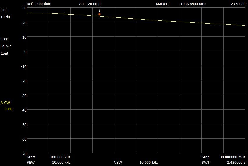
Measured Preamp Gain 100KHz to 30 MHz (50 ohm load, 12 Vdc)
Gain at 10 MHz measures approximately 24 dB
Far Circuits wd8dsb WWV TRF receiver circuit board top and bottom views
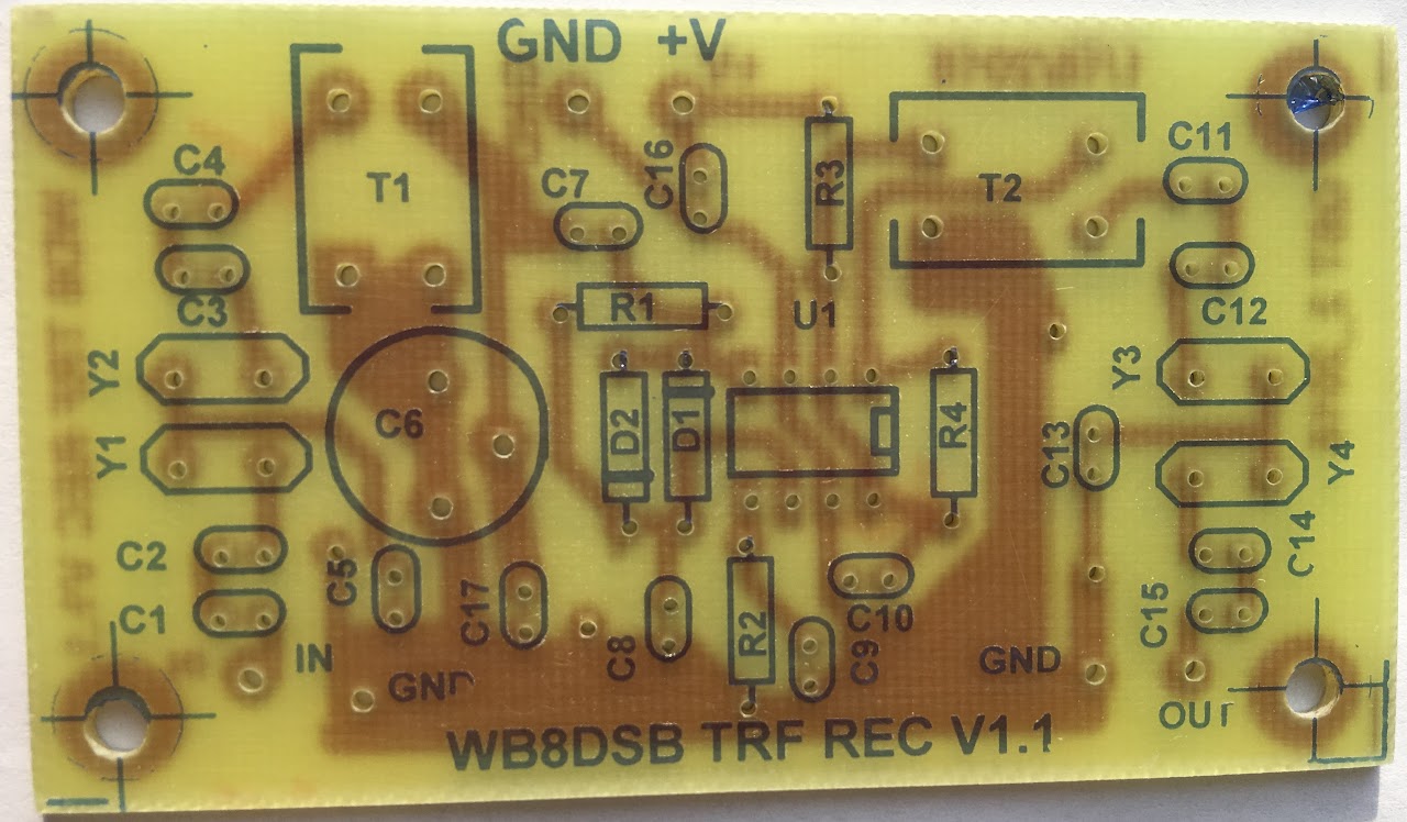
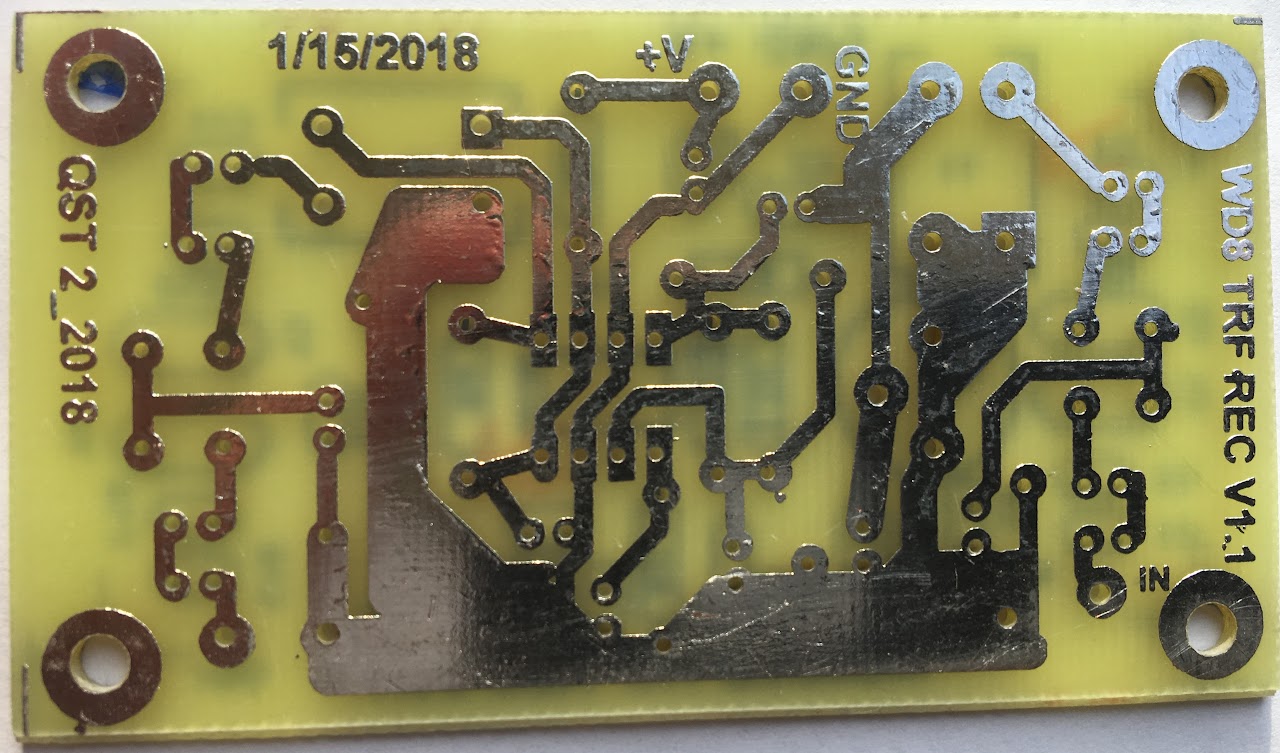
Note: C17 is rotated 90 degrees compared to my original circuit board design, and the mounting hole spacing is slightly different. Component identification is identical to my original design.
Far Circuits wd8dsb TRF receiver preamp circuit board top and bottom views
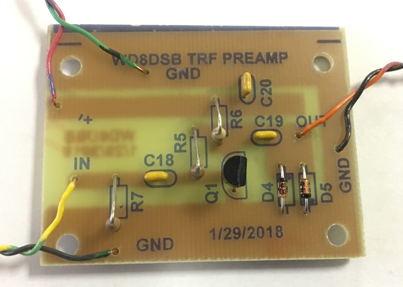
Preamp Build Picture
Below are some helpful tips/ideas, and I will add to the list as needed.
Direct Calibration (Tip #1)
For maximum gain (maximum signal into the frequency counter), the 50 ohm termination shown in Figure 2 of the article can be eliminated if the connection between the preamp and the frequency counter is kept very short. I prefer to use BNC adapters to make this connection, but a very short piece of coax (18 inches or less) will also work (anything longer may cause excess signal distortion due to reflections).
Note: The preamp voltage gain into a 50 ohm load is approximately 26 dB (at 10 MHz), and it increases to a maximum value of 40 dB when the load impedance is increased toward infinity (already 40 dB when the load is 1 K). Therefore elimination of the termination resistor can be very helpful when signals from WWV are marginal.
Direct Calibration (Tip #2)
The receive antenna should be located a reasonable distance away from the frequency counter, otherwise the receive antenna may encounter interference from signal leaking out of the frequency counter which can happen if the frequency counter does not have a well shielded case. My home brew frequency counter is in a plastic case, and when using an attic antenna I often have to wrap my frequency counter in aluminum foil to prevent false readings (readings higher than the actual WWV frequency). This is never an issue when using a receive antenna that's located in my backyard that's 50 feet away from my frequency counter.
What WWV frequency is best for your location and time of day (Tip #3)
There is a very good online program called VOACAP that can be used to create a map showing the estimated coverage area of WWV as follows:
Select TX QTH: Denver Co
Select RX QTH: City closest to your QTH, or enter in your coordinates
Select CW
Select 1500 Watts
Select 30 Meter Transmitter Site TX Antenna: 1/4 wl vert Gd Gnd
Select 60 Meter Transmitter Site TX Antenna: 1/4 wl vert Gd Gnd
Select 30 Meter Receiver Site RX Antenna: 1/4 wl vert Gd Gnd
Select 60 Meter Receiver Site RX Antenna: 1/4 wl vert Gd Gnd
Click on Antennas Tab to make it disappear
Click on Settings
Select Noise: Residential
Select Band: 30 meters for 10 MHz WWV or 60 meters for 5 MHz WWV
Select UTC for start time to analyze
Select Range: 12 hours (to generate 12 individual charts, 1 chart per hour)
Click on Settings to make the Settings menu disappear
Scroll to bottom of page and select REL map then wait while all 12 hour charts are generated.
Alternative power source for the TRF Preamp (Tip #4)
A 9 volt alkaline battery works well as an alternative power source for the broadband preamp.
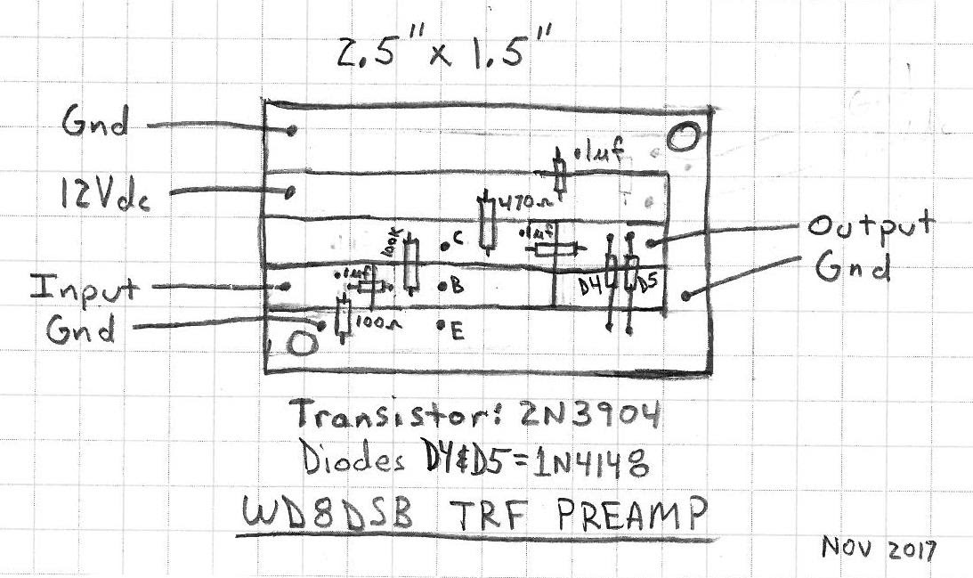
Preamp Board Layout (Tip #5)
Here is the recommended pattern and parts layout for the broadband preamp board that's made using a Dremel tool with thin cutoff wheel. The overall board dimension is 2.5" x 1.5" (grid lines every 0.25")
(Click on Images Below To Zoom In)
BasicPCB.com circuit board ordering of TRF board (Tip #6)
If ordering circuit boards from basicpcb.com, you will need to upload a .zip file to basicpcb.com that contains all of the TRF circuit board artwork. The Zip file is called WD8DSB WWV TRF RECEIVER Rev1.1.zip and you can download it at the bottom of this page, then you need to map the files in the .zip file as follows after you upload the .zip file to basicpcb.com:
BoardOutline.gbr = Drawing Other
Bottom.gbr = Bottom Copper
BottomAssy = Drawing Other
BottomDimension = Drawing Other
BottomMask = Bottom Soldermask
BottomPaste = Bottom Solderpaste
BottomSilk = Bottom Silkscreen
Drill_NonPlated_Through = Non Plated Drill
Drill_Plated_Through = Drawing Other
Through = NC Drill
Top = Top Copper
TopAssy = Drawing Other
TopDimension = Drawing Other
TopMask = Top Soldermask
TopPaste = Top Solderpaste
TopSilk = Top Silkscreen
Alternative sources for the MC1350P (Tip #7)
Besides Jameco, the NTE746 is the equivalent of the MC1350P, but typically at a much higher price.
Questions From Readers Of My QST Article
Question: "why you used capacitors 1-4 like you did, instead of just using two"
Answer: Great question. C1 and C2 could be one capacitor, as could C3 and C4, but you can get slightly smaller changes in capacitance if you don't combine the two capacitors (I will provide an example lower down in this E-mail).
You will notice that C2, C3, and C5 are all the same value. They are calculated based on the desired filter bandwidth and pass band ripple, using the measured motional inductance or measured motional capacitance, and the calculated series frequency of the crystal. But the series frequency of these parallel crystals is actually lower than 10 MHz, and therefore the center frequency of the crystal filter will be lower than 10 MHz. Then you need to shift the center frequency of the filter upwards, and that is what C1 and C4 really do.
Therefore the best way to look at the filters is that C2, C3, and C5 establish the bandwidth of the filter, whereas C1 and C4 are used to adjust the center frequency of the filter.
Now lets look if C1 and C2 were just one capacitor. For my 10 MHz receiver C1 = 36 pf, and C2 = 220 pf, and when combined in series they actually have a value of 30.94 pf
You will notice that I said C1 could be 39 pf to better center the filter, so if C1 = 39 pf, and C2 = 220 pf, in series they look like a capacitor of 33.13 pf.
The difference in capacitance is 33.13 pf - 30.94 pf = 2.19 pf. We were able to make a change in capacitance of 2.2 pf, whereas if you used just a single capacitor you would be able to make changes in increments of 3 pf or greater (based on what's typically available). Not much difference, but not combining the capacitors does provide slightly more resolution in available capacitance changes.
Again, nothing wrong with combining the two capacitors into just one capacitor, but I prefer to consider C1 and C4 as tuning capacitors to shift the center frequency of the filter, whereas C2, C3, and C5 set the bandwidth and passband ripple, and my method provides slightly smaller incremental changes.
Note: For the 5 MHz receiver, using C1 and C2 versus one capacitor for the two provides incremental changes of 1.7 pf versus increments of 3 pf when using capacitors in 3 pf increments for C1.
Note: it's always interesting to plot your TRF receiver passband (I would certainly be interested). Just use a stable function generator along with a 50 ohm attenuator to feed a very small sinewave (inject a signal somewhere between 50 uV and 1000 uV rms) into the TRF receiver, and with the output of the TRF receiver terminated into a 50 ohm load measure the output of the receiver using your scope as you change the function generator frequency from slightly below to slightly above 10 MHz (or 5 MHz for the 5 MHz receiver) in approximately 100 Hz increments, and then plot the results.
Question: "I have my board for 10MHz almost fully populated but for T1 and T2. After winding those I realized that I wasn't sure which side the primary turns connect to."
Answer: For T1 the primary connects to C4 and the ground bus, and for T2 its primary connects to U1 pin 1 and U1 pin 2.
Another way to look at it is as follows.
For T1, the left line on the T1 silk screen represents the primary for T1.
For T2, the top line on the T2 silk screen represents the primary for T2.
Note: Maybe the best way to know which is the primary and which is the secondary winding in the schematic would be as follows: All transformers are drawn so their primary is shown as the left winding, and the secondary is drawn as the right winding on the schematic.
Question: "Are the crystals connected to the ground bus?"
Answer: Yes the crystal cases connect to ground. It's typically a good idea to connect the cases to ground, and I included that in my design. You can click on the picture of my build that's shown above to zoom in, and then you can click again to zoom in even closer which will show the grounding of the crystals in greater detail.
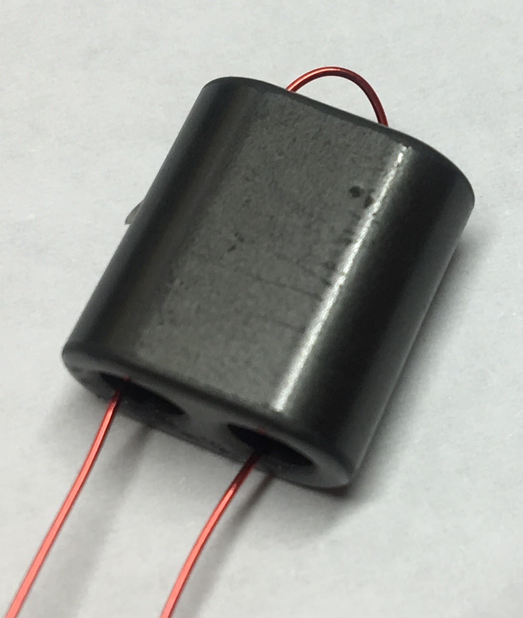
Question: "For the binocular cores, do you count one pass through one hole as one turn?"
Answer: No, one complete turn on the binocular core requires the wire to pass through both holes in the core one time as shown in the picture below.
Question: "Besides Amidon what alternative sources do you use for the T2, T3, and T4 transformer cores?"
Answer: Mouser is another good source for these cores using the Fair Rite part number shown below.
FT50-43: Fair Rite part number 5943000301
BN73-202: Fair Rite part number 2873000202
Question: "How accurate to NIST is the received signal?"
Answer: My home built frequency counter with a TCXO clock has a resolution of 1 Hertz (using 1 second gate time), and as long as I don't encounter fade I typically only see a variation in frequency measurement of WWV on 5 and 10 Mhz by 1 digit (1 Hz) and impossible for me to tell if that's mostly due to doppler effect caused by the ever variable Ionsphere, or quantization error within my frequency counter. Data acquired by Connie Marshall (K5CM) indicates an accuracy of 1 Hz is reasonable during most times of day, with the exception possibly being around Sunrise and Sunset. Per Connie, "As long as you stay away from "sundown and sunrise" Doppler is usually less than 1 Hz.". Connie's data suggests the variation is +/- 0.2 Hz in the mid afternoon at his location in Oklahoma.
Link to Connie's data showing effect of Doppler on the 5 and 10 MHz WWV signal mid afternoon in Oklahoma http://www.k5cm.com/wwv-doppler-corr.htm
Link to Connie's data showing Sunrise and Sunset effect on the CHU Canada signals (3.33 & 7.85 MHz) in Oklahoma due to Doppler http://www.k5cm.com/chu.htm
Some Build Pictures From QST Readers Using Different Enclosures
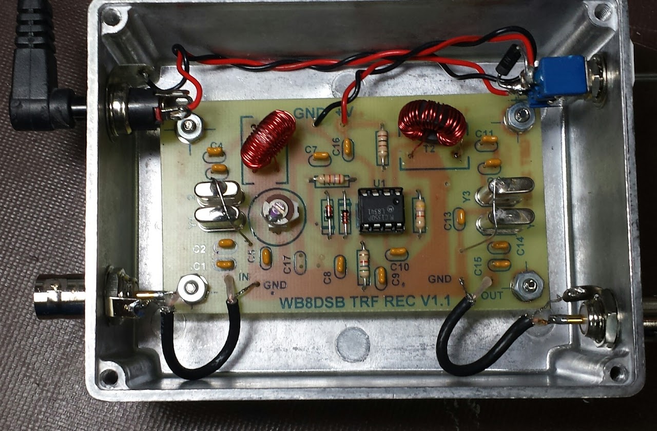
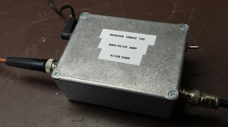
Jim Cook (W8NSA) 10 MHz WWV TRF Receiver Build, Die-Cast Enclosure (Mouser 563-CU-471)
Jim provided the following comments about his build: The box is Bud, CU-471, 4.33" X 3.25" X 1.59" Used steel 4-40 hex standoffs 0.375" long to mount the board. RG-174 used on the RF input and output.
I had an issue with the coaxial power jack, It appeared to me using the plug I hand on hand there was no continuity between the outer barrel of the plug and jack on any of the solder tabs on the jack. As I had continuity between the body of the jack and plug barrel I used an additional ring solder tab on the jack for the negative, puts my case the negative power supply rail. The small bench supply I'm using for 12v is not referenced to earth/ground, the box ground is from the input RF cable and any instrument I'm using on the output of the receiver.
I've had no instability or oscillation issues with the build at all at a measured 43 dB of gain.
I mounted the Schottky diode across the N.C lugs when OFF position on the switch, power leads twisted and tucked down and away from the board.
Joel Weder (VE6EI) 10 MHz WWV TRF Receiver Build (small Hammond 1411G box)
Joel encountered an oscillation problem when he put his build in the following small box. We were concerned that his twisted wires were laying to close to components on the circuit board when he closed the lid. He was able to solve his oscillation problem as follows: I just fired up the TRF receiver again, sealed up in its little box, and it's working perfectly this time. I shortened the wires and added a couple more twists to each. I also added a .01 uF capacitor to the power supply input, directly on the board. I realize you designed it with a 0.1 uF cap, but felt it might benefit from a little more bypassing.
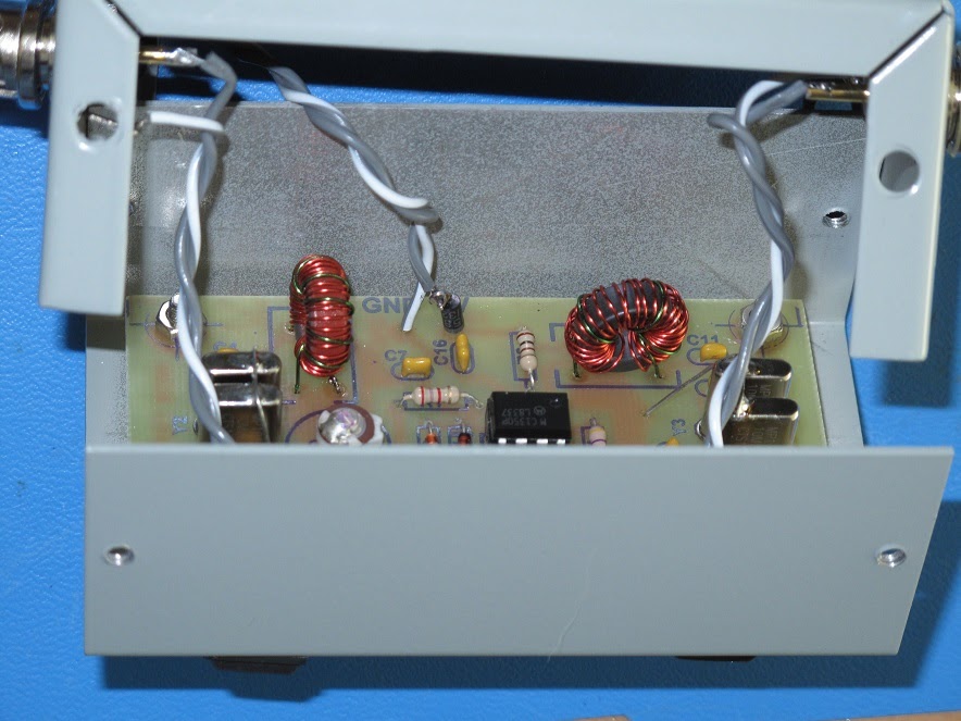
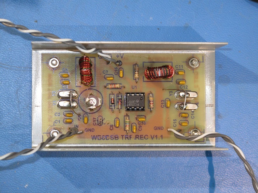
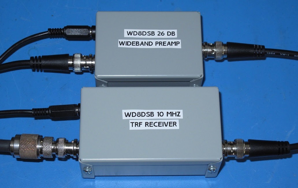
The TRF receiver is in a Hammond 1411G, 4.0 x 2.2 x 1.6, and the preamp is in a Hammond 1411C, 3.2 x 2.2 x 1.1"
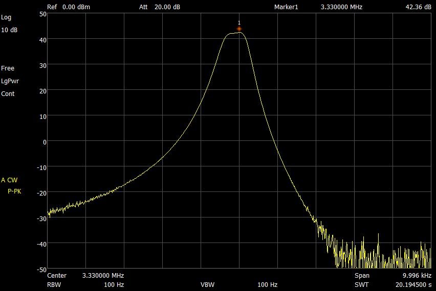
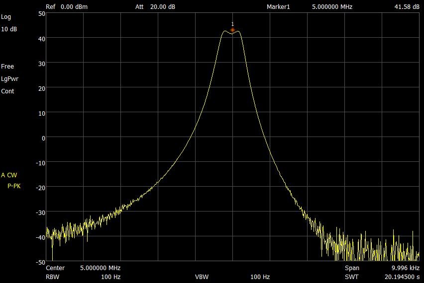
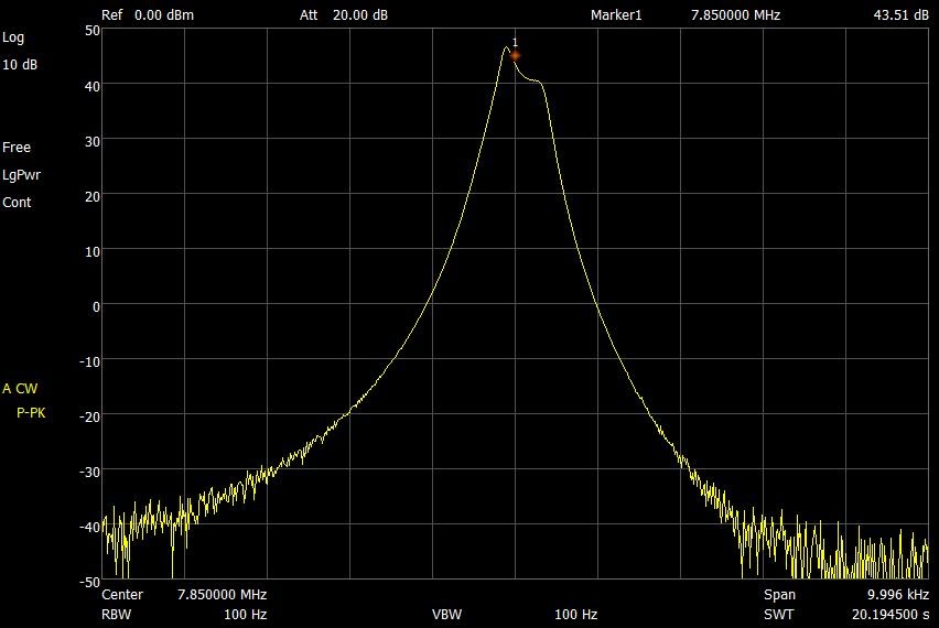
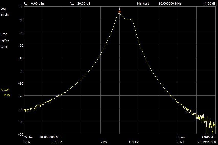
WD8DSB 3.33, 5, 7.85 and 10 MHz TRF Receivers measured April 23, 2020 using Spectrum Analyzer
(website created and maintained by Don Kirk (wd8dsb), January 3, 2018)
